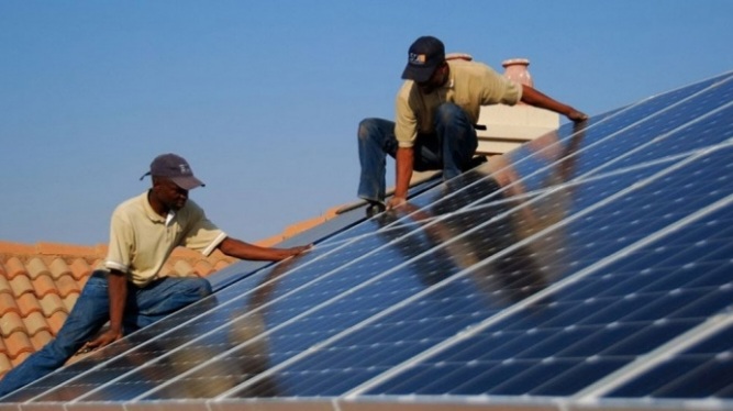
DC and AC Protection Coordination in Solar PV Installations: Fuse Selection, Circuit Breakers, Surge Protection Devices, and Earthing Systems
Introduction
A solar PV installation is only as safe and reliable as its electrical protection system. High-quality solar panels, a reliable inverter, and a properly designed battery bank cannot guarantee safety if the protective devices are incorrectly selected or installed.
DC and AC protection coordination involves more than installing fuses, circuit breakers, and surge protection devices. It requires selecting the right components, positioning them correctly, and ensuring they work together to protect cables, equipment, and people against electrical faults.
This guide explains the essential principles of protection coordination in solar PV installations, covering PV string fuses, DC circuit breakers, battery protection, AC distribution protection, surge protection devices, earthing, bonding, and practical commissioning procedures.
1. Understanding Protection Coordination in Solar PV Systems
Protection coordination is the process of selecting and arranging protective devices so that they respond appropriately when an electrical fault occurs.
For example, if a fault develops in one PV string, the protection system should isolate the affected circuit where the design permits, without unnecessarily interrupting power to the rest of the installation.
Effective protection coordination requires consideration of:
- Maximum operating current.
- Prospective short-circuit current.
- Equipment voltage ratings.
- Cable current-carrying capacity.
- Fuse and circuit-breaker characteristics.
- Breaking capacity.
- Selectivity between protective devices.
- Surge protection requirements.
- Earthing and bonding arrangements.
- Manufacturer recommendations and applicable electrical standards.
DC and AC circuits behave differently during faults. DC circuits do not have the natural current zero crossings that help extinguish AC arcs. Consequently, a protective device designed for AC operation must not automatically be assumed suitable for DC applications.
The protection system should be designed as an integrated part of the installation rather than treated as an accessory added after the main equipment has been connected.
2. DC Protection: PV String Fuses, Circuit Breakers, and Isolators
The DC side of a solar installation includes PV modules, string cables, combiner boxes, DC isolators, charge controllers, battery circuits, and inverter DC inputs.
Each circuit has specific protection requirements based on its operating current, voltage, cable characteristics, and potential fault conditions.
2.1 PV String Fuse Selection
When multiple PV strings are connected in parallel, current from healthy strings may flow back into a faulty string. Depending on the system configuration, this reverse current can damage modules and cables.
String fuses may therefore be required to protect individual strings against excessive reverse current.
Before selecting a fuse, check the PV module datasheet for:
- Maximum series fuse rating.
- Short-circuit current (Isc).
- Maximum power current (Imp).
- Maximum system voltage.
- Manufacturer-specified protection requirements.
Consider a PV string with a short-circuit current of 13 A. If the applicable design method requires a current factor of 1.25, the preliminary calculation is:
Design current = 13 A × 1.25 = 16.25 A.
This result is a design input, not an automatic instruction to install a 16.25 A fuse. The final selection must comply with the applicable standard and account for module fuse limits, cable ampacity, fuse characteristics, and expected fault conditions.
The fuse must also have an appropriate DC voltage rating and breaking capacity. PV string voltage calculations must account for the increase in open-circuit voltage that occurs at low temperatures.
Not every PV installation requires string fuses. Their necessity depends on the number of parallel strings, possible reverse current, module specifications, and the applicable design requirements.
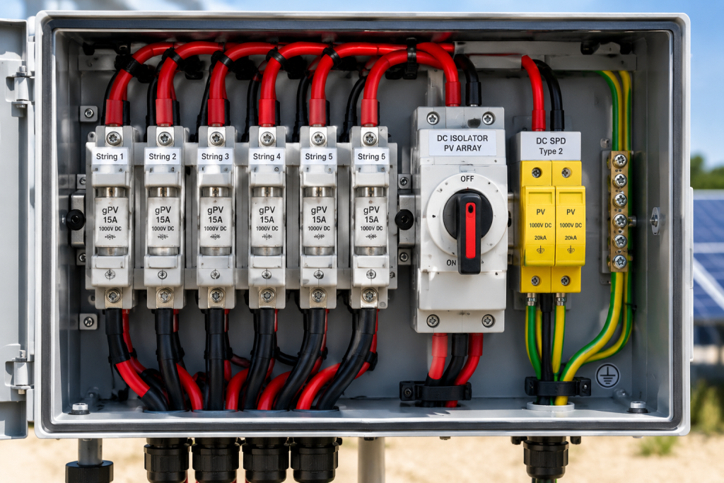
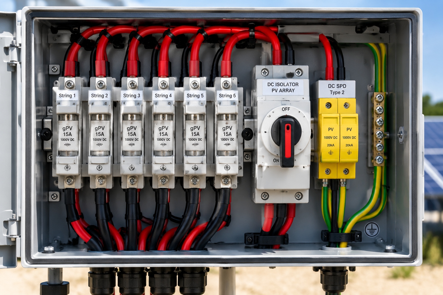
Image: PV string fuses installed in a solar combiner box.
2.2 DC Circuit Breakers and Isolators
DC circuit breakers protect suitable circuits against specified overload and short-circuit conditions. DC isolators provide a means of disconnecting equipment for maintenance and servicing.
When selecting a DC circuit breaker, verify:
- Rated DC voltage.
- Rated current.
- DC breaking capacity.
- Trip characteristics.
- Compatibility with the circuit.
- Manufacturer installation requirements.
An ordinary AC circuit breaker must not be used on a DC circuit unless it is specifically rated and approved for that DC application. Otherwise, it may be unable to interrupt a DC arc safely.
The distinction between a circuit breaker and an isolator is equally important. An isolator does not necessarily provide overload or short-circuit protection.
For outdoor installations, the isolator enclosure must be suitable for the environment, with appropriate protection against moisture, dust, and other site conditions. The device should also be accessible and clearly labelled.
3. Battery Protection in Off-Grid and Hybrid Solar Systems
Battery circuits require particular attention because batteries can deliver very high fault currents, especially when multiple batteries are connected in parallel.
A short circuit involving a battery cable can cause severe overheating, arcing, burns, or fire.
Battery protection should account for inverter demand, battery discharge limits, cable ampacity, surge requirements, fuse breaking capacity, and manufacturer recommendations.
3.1 Calculating Battery Current
The approximate continuous DC current required by an inverter can be estimated using:
DC current = AC output power ÷ (Battery voltage × Inverter efficiency)
For example, consider a 5,000 W inverter operating from a nominal 48 V battery bank with an assumed efficiency of 90%.
DC current = 5,000 ÷ (48 × 0.90)
DC current ≈ 115.7 A.
This calculation provides an initial estimate. The final protection design must also consider the inverter’s actual DC operating-voltage range, maximum input current, surge requirements, battery specifications, and cable rating.
The fuse must carry the expected operating current while providing the required protection to the cable and equipment. Its DC breaking capacity must be adequate for the available fault current.
3.2 Battery Fuse Placement
Battery overcurrent protection should generally be installed as close as practicable to the battery’s positive terminal, in accordance with the applicable installation standard and manufacturer instructions.
This reduces the length of unprotected conductor between the battery and the protective device.
In installations with multiple parallel batteries, individual battery branches may require separate protection, depending on the system design and applicable requirements.
Battery interconnection cables must also be correctly sized, and the arrangement should support appropriate current sharing.
3.3 Battery Disconnects
A battery disconnect allows the battery bank to be isolated for maintenance or emergency procedures.
The disconnect must be suitable for the battery system’s DC voltage, current, and switching requirements. A standard AC switch must not be assumed suitable for a high-current battery circuit.
Image: Battery protection equipment and high-current DC connections.
4. AC Protection: Circuit Breakers and Distribution Boards
The AC side of a solar installation may include the inverter output, utility grid connection, generator input, changeover switches, distribution boards, and circuits supplying lighting, sockets, pumps, and appliances.
AC protection must be designed to protect cables, equipment, and people against electrical faults.
4.1 Selecting AC Circuit Breakers
When selecting an AC circuit breaker, consider:
- Expected operating current.
- Cable current-carrying capacity.
- Rated system voltage.
- Prospective short-circuit current.
- Breaking capacity.
- Trip characteristics.
- Required number of poles.
- Coordination with upstream and downstream devices.
The breaker must be suitable for the fault level at its installation point. A device with insufficient breaking capacity may fail to interrupt a fault safely.
For example, if the prospective short-circuit current at a distribution board is 6 kA, the protective device must have an adequate breaking capacity for that fault level under its specified operating conditions.
The actual fault level must be determined from the installation design. Utility supplies, transformers, generators, and inverter systems may contribute differently to the available fault current.
4.2 Protection Between the Inverter and Distribution Board
A typical installation may include a dedicated AC protective device between the inverter output and the distribution board.
The rating must match the inverter’s specifications, expected current, cable ampacity, and installation requirements.
Where the system includes a grid connection, generator input, or automatic changeover arrangement, the protection design must account for the different operating modes and possible sources of fault current.
Selectivity between protective devices should be verified using manufacturer data, time-current curves, and the expected fault conditions. Simply installing a smaller breaker downstream does not guarantee that it will operate first.
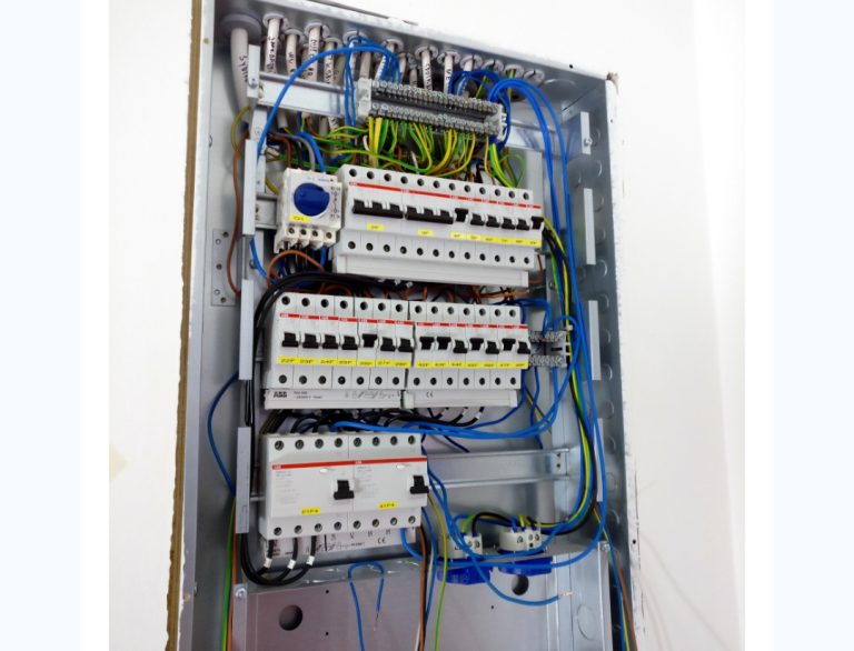
Image: AC circuit breakers and distribution equipment used in solar installations.
5. Surge Protection Devices in Solar PV Installations
Surge protection devices (SPDs) help protect solar equipment against transient overvoltages caused by lightning-related activity and electrical switching events.
Because PV arrays are commonly installed outdoors and may have long cable runs, surge protection deserves careful consideration during system design.
An SPD can reduce the risk of equipment damage, although it cannot guarantee protection against every lightning-related event.
5.1 Understanding SPD Types
The main SPD classifications include:
- Type 1: Designed for applications requiring protection against partial lightning current.
- Type 2: Commonly used to protect electrical installations against induced surges and switching overvoltages.
- Type 3: Used as supplementary protection close to sensitive equipment where appropriate.
These types are intended for different applications and must not be treated as interchangeable.
The correct arrangement depends on the installation’s lightning risk assessment, external lightning protection system, supply configuration, equipment requirements, and applicable standards.
5.2 DC Surge Protection
A DC SPD may be installed on the PV side to limit transient overvoltages reaching the inverter or other connected equipment.
When selecting a PV SPD, verify:
- Maximum continuous operating voltage.
- Compatibility with the maximum PV string voltage.
- Voltage protection level.
- Surge current rating.
- SPD type and test classification.
- Compatibility with the system’s earthing arrangement.
- Manufacturer installation requirements.
The SPD must be suitable for the PV system’s actual configuration. The maximum continuous operating voltage must not be selected using the nominal system voltage alone.
5.3 AC Surge Protection
An AC SPD may be installed at the main distribution board or another suitable point to protect equipment against transient overvoltages.
Additional protection may be appropriate where long cable runs or sensitive equipment increase exposure to surges.
The required arrangement depends on the installation’s risk assessment, supply system, and applicable standards.
5.4 Correct SPD Installation
Even a high-quality SPD may provide inadequate protection if it is installed incorrectly.
Important installation considerations include:
- Keeping connecting conductors as short and direct as practicable.
- Following the manufacturer’s specified conductor sizes and connection arrangement.
- Providing required upstream overcurrent protection.
- Connecting the SPD to the appropriate protective earthing or bonding point.
- Ensuring the enclosure suits the installation environment.
- Checking status indicators and following replacement instructions.
Long connecting conductors can increase the effective voltage appearing at the protected equipment during a surge.
Image: Surge protection devices used to reduce transient overvoltage risks.
6. Earthing and Bonding in Solar PV Systems
Earthing and bonding are essential elements of electrical safety, but they serve related yet distinct purposes.
Earthing connects designated parts of an electrical installation to the earth through the prescribed protective earthing arrangement. Protective bonding connects exposed conductive parts and other required conductive elements to help maintain appropriate equipotential conditions.
The correct arrangement depends on the electrical supply system, inverter design, battery configuration, and applicable regulations.
6.1 Equipment Earthing
Depending on the system design and applicable requirements, exposed conductive parts requiring protective earthing or bonding may include:
- Inverter metal enclosures.
- Metal distribution boards.
- PV module frames.
- Mounting structures.
- Equipment cabinets.
The manufacturer’s instructions must be followed, as not every metal component should be connected in the same way.
Protective earthing of exposed metal parts must also be distinguished from connecting a PV DC conductor to earth. Some transformerless inverters require the PV DC side to remain unearthed. An unauthorised connection between a PV positive or negative conductor and earth may cause faults or interfere with the inverter’s protection functions.
6.2 Neutral-Earth Bonding
Neutral-earth bonding is one of the most misunderstood aspects of hybrid and off-grid solar installations.
The correct arrangement depends on the inverter design, utility supply, generator configuration, and the way the system switches between operating modes.
Some inverters establish a neutral-earth connection in island mode, while other designs require different arrangements.
An incorrect connection may cause unwanted current through protective conductors, residual-current device problems, or unsafe conditions during a fault.
Before making a neutral-earth connection, check the inverter and generator documentation and verify compliance with the applicable electrical regulations.
6.3 Earth Electrodes and Testing
Where an earth electrode is required, it must be installed and tested using an appropriate method.
However, a low earth-resistance reading alone does not prove that the entire installation is safe. Protective-conductor continuity, bonding, fault-disconnection performance, and the operation of protective devices must also be assessed.
Image: Protective earthing and bonding components in an electrical installation.
7. Residual-Current Devices (RCDs)
Residual-current devices can provide additional protection against electric shock and certain earth-leakage faults when correctly selected and installed.
Different RCD types respond to different residual-current waveforms. Some inverter designs can produce residual currents containing DC components, so the correct RCD type must be determined from the inverter manufacturer’s instructions and applicable standards.
It is not safe to assume that a Type AC, Type A, Type F, or Type B device is automatically suitable for every solar installation.
Where an inverter includes residual-current monitoring, the installation requirements must still be checked to determine whether additional external protection is needed.
During commissioning, the required RCDs should be tested using an appropriate instrument and procedure. A test button provides a basic functional check but does not replace instrument-based testing where required.
8. Coordinating Fuses, Circuit Breakers, SPDs, and Earthing
For effective protection coordination, the following process provides a useful starting point.
Step 1: Identify All Power Sources
Identify every source that can supply current to the installation, including the PV array, battery bank, utility grid, generator, and any other connected source.
Each source may contribute differently to a fault.
Step 2: Calculate Design Currents
Determine expected operating currents and identify the maximum permitted current for cables and equipment.
For PV circuits, consider temperature-corrected voltage, operating current, and possible reverse current from parallel strings.
For battery circuits, consider inverter demand, battery discharge limits, surge requirements, and possible fault current.
For AC circuits, calculate expected loads and assess prospective fault current where required.
Accurate solar sizing is an important starting point for selecting system components and identifying protection requirements. The GLOBISUN Solar App provides solar system calculation tools to help installers with their design work.
Step 3: Verify Cable Ampacity
Select cable sizes based on current-carrying capacity, voltage drop, installation method, ambient temperature, grouping, insulation type, and other relevant derating factors.
Protective devices must be coordinated with the cables so that the cables are adequately protected under the applicable overload and fault conditions.
Step 4: Confirm Protective Device Ratings
For each fuse and circuit breaker, verify its rated voltage, rated current, breaking capacity, trip characteristics, application suitability, and coordination with other protective devices.
Current rating alone is not enough to establish suitability.
Step 5: Assess Selectivity
Where practical, arrange the protection so that the device nearest to a fault operates before upstream devices.
Verify selectivity using manufacturer coordination tables, time-current curves, and the available fault current.
Step 6: Verify SPD Coordination
Choose suitable SPD types and voltage ratings for the installation. Check whether upstream protection is required and ensure that the SPD is compatible with the earthing arrangement.
Step 7: Verify Earthing and Bonding
Confirm protective-conductor continuity, bonding of required exposed conductive parts, and the correct neutral-earth arrangement for the inverter’s operating modes.
Step 8: Test the Completed Installation
Complete the required inspection and electrical tests before energising the system.
Depending on the installation, these may include protective-conductor continuity, insulation resistance, polarity, earth-electrode measurements, fault-loop or automatic-disconnection checks, RCD testing, and functional testing.
Testing must follow the applicable electrical standard and the equipment manufacturer’s commissioning instructions.
9. Common Protection Mistakes Solar Installers Should Avoid
The following mistakes can compromise the safety and reliability of a solar installation.
- Using AC breakers on DC circuits without verifying their DC suitability.
- Selecting PV fuses without checking module specifications.
- Ignoring the available fault current from battery banks.
- Installing undersized cables.
- Choosing SPDs based only on voltage rating.
- Making unnecessary neutral-earth connections.
- Assuming an earth electrode alone guarantees safety.
- Ignoring coordination between protective devices.
- Skipping commissioning tests.
- Copying another installation’s protection arrangement without checking equipment compatibility.
Protection devices must be selected for the actual installation. Two systems with similar inverter ratings may have different battery characteristics, earthing arrangements, cable routes, and fault levels.
10. Practical Solar PV Protection Commissioning Checklist
Before handing over a solar PV installation, use a checklist appropriate to the system design and applicable regulations.
DC Side
- Confirm PV string voltage and current against inverter limits.
- Verify temperature-corrected PV voltage calculations.
- Check that string fuses are installed where required.
- Verify fuse ratings, DC voltage ratings, and breaking capacity.
- Confirm DC breakers and isolators are suitable for their intended functions.
- Inspect DC cable sizing, polarity, connectors, and routing.
- Verify battery fuse and disconnect ratings.
- Check battery cable sizing and terminal connections.
AC Side
- Verify inverter output protection.
- Check circuit-breaker ratings and breaking capacity.
- Confirm cable ampacity and voltage-drop calculations.
- Check generator and changeover arrangements where applicable.
- Verify neutral switching and neutral-earth arrangements.
- Confirm RCD selection and complete the required tests.
Surge Protection
- Confirm whether DC and AC SPDs are required.
- Verify SPD types and voltage ratings.
- Inspect connection lengths and conductor routing.
- Confirm earthing connections and upstream protection.
- Check SPD status indicators.
Earthing and Bonding
- Verify protective-conductor continuity.
- Inspect bonding of required exposed conductive parts.
- Complete earth-electrode tests where applicable.
- Verify neutral-earth configuration against manufacturer instructions.
- Carry out the required fault-protection tests.
Documentation and Handover
- Record protective-device specifications.
- Keep copies of relevant test results.
- Label isolators, protective devices, and power sources.
- Provide operating and emergency shutdown instructions.
- Document maintenance requirements and installation limitations.
This checklist should be adapted to the equipment installed and the electrical standards applicable to the project.
Conclusion
DC and AC protection coordination is fundamental to a safe, reliable solar PV installation.
Fuses protect against specified overcurrent conditions, circuit breakers provide switching and fault-protection functions according to their design, surge protection devices help limit transient overvoltages, and earthing and bonding support the installation’s protective measures.
These components must work together as part of a coordinated electrical design.
The process begins with accurate calculations, continues with the correct selection of cables and protective devices, and concludes with inspection, testing, and proper documentation.
For solar installers, the objective is not simply to make a system work. It is to ensure that it operates safely, protects people and equipment, and remains reliable over the long term.
Always consult equipment manufacturers’ documentation and applicable electrical standards. Where fault levels, earthing arrangements, or inverter and generator integration require specialist assessment, involve a qualified electrical professional.