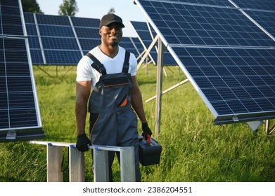
Hybrid Solar System Integration and Commissioning: Grid Synchronisation, Generator Integration, Neutral-Earth Bonding, Changeover Systems, and Functional Testing
Introduction
When I install or design a hybrid solar system, I pay attention to more than just connecting solar panels, batteries, and an inverter. I also consider how every power source will work together, how the system will respond when one source fails, and how to ensure that the entire installation operates safely and reliably.
A hybrid solar system may combine solar photovoltaic (PV) generation, battery storage, utility power, and a standby generator. Each source has its own operating characteristics, and integrating them correctly requires careful planning, proper equipment selection, and thorough commissioning.
In my experience, one area installers must never overlook is the relationship between the inverter, the utility supply, the generator, the neutral conductor, and the earthing system. A mistake in any of these areas can cause inverter faults, unexpected shutdowns, nuisance tripping, equipment damage, or serious electrical hazards.
In this guide, I will explain the key considerations I use when approaching hybrid solar system integration and commissioning, including grid synchronisation, generator integration, neutral-earth bonding, changeover systems, electrical protection, and functional testing.
My goal is to help solar installers understand not only how to connect a hybrid solar system, but also how to verify that it works correctly under different operating conditions.
1. Understanding Hybrid Solar System Architecture
Before I begin any installation, I first identify the system architecture and confirm how each component is expected to operate.
A typical hybrid solar installation may include:
- Solar photovoltaic modules
- PV combiner boxes and DC protection devices, where required
- Hybrid inverter or inverter-charger
- Battery energy storage system
- Utility grid connection
- Standby generator, where required
- Essential and non-essential load distribution boards
- AC and DC isolators
- Circuit breakers and protective devices
- Earthing and bonding conductors
- Changeover or transfer equipment, where required
- Energy meters, current transformers, and monitoring devices
I do not assume that every hybrid inverter supports the same functions. Some models can accept generator power through a dedicated AC input, while others require a separate transfer arrangement. Some provide an integrated backup output, while others have different connection requirements.
I always check the inverter’s wiring diagrams and technical manual before deciding how to connect the different power sources.
Understanding the operating modes
I normally consider the following operating modes when designing or commissioning a hybrid solar system.
Solar-priority mode
In this configuration, solar energy supplies the loads first. Any excess energy may charge the battery or be exported to the utility if the inverter supports export and the installation is permitted to do so.
Battery-discharge mode
When solar generation cannot meet the load demand, the battery supplies the shortfall according to the configured operating priorities and minimum state-of-charge limits.
Grid-support mode
When solar and battery power are insufficient, the utility supplies some or all of the remaining demand.
Backup mode
When the utility supply fails, a compatible hybrid inverter isolates the designated backup loads from the utility and supplies them using available solar and battery energy.
Generator-support mode
Where the inverter supports generator integration, a standby generator can supply an approved AC input, support the loads, or charge the battery.
Understanding these operating modes helps me determine the appropriate wiring arrangement, protection requirements, and commissioning tests before energising the system.
2. How I Approach Grid Synchronisation
Grid synchronisation is an important part of integrating a grid-connected hybrid inverter.
Before an inverter operates in parallel with the utility supply, its control system must ensure that its AC output is compatible with the grid. This generally involves voltage, frequency, phase angle, and phase sequence where applicable.
I always confirm that the inverter is configured for the correct supply characteristics and approved grid-interconnection requirements.
2.1 Voltage compatibility
For a typical single-phase installation using a nominal 230 V supply, I confirm that the inverter is designed for that voltage and that its grid settings match the applicable requirements.
For a three-phase installation, I verify the relevant line-to-line and line-to-neutral voltages and confirm that the inverter supports the site’s supply arrangement.
I also check the manufacturer’s specified operating limits.
Incorrect voltage settings can prevent synchronisation or cause repeated disconnection. Where voltage problems occur, I investigate the actual supply conditions and installation rather than immediately changing the inverter’s protection settings.
2.2 Frequency compatibility
In a 50 Hz electrical system, I confirm that the inverter is configured for the correct nominal frequency and approved operating limits.
If the grid frequency moves outside the permitted range, the inverter may reduce its output or disconnect.
I do not recommend widening frequency protection limits simply to stop an inverter from disconnecting. I first establish whether the problem comes from the utility supply, an unsuitable generator, incorrect configuration, or another installation fault.
2.3 Phase configuration
For three-phase systems, I verify the phase arrangement and phase sequence where required.
Incorrect phase identification can affect three-phase loads, metering, protection, and equipment that depends on phase rotation.
I also check that the inverter’s connection diagram matches the actual wiring arrangement.
2.4 Understanding grid-following and grid-forming operation
One distinction I consider important is the difference between grid-following and grid-forming operation.
During normal grid-connected operation, the inverter generally follows the utility’s voltage and frequency while controlling its power output.
During backup operation, a compatible inverter may establish its own controlled AC supply for designated loads. This is known as grid-forming operation.
The transfer arrangement must ensure that the backup output cannot unintentionally energise the utility network during an outage.
I never assume that a backup output can be connected directly to a grid connection. I follow the manufacturer’s approved wiring arrangement and confirm that the required isolation and transfer functions are in place.
3. How I Integrate a Generator with a Hybrid Inverter
When I design a hybrid system for a location with unreliable utility power, I consider whether a generator is necessary to provide additional backup during extended periods of low solar production.
However, I do not select a generator based on its advertised capacity alone. I also consider voltage regulation, frequency stability, load characteristics, battery-charging demand, and compatibility with the inverter.
3.1 What I check before connecting a generator
Before approving a generator for integration, I verify:
- Rated voltage and frequency
- Single-phase or three-phase configuration
- Continuous and standby power ratings
- Voltage regulation under changing loads
- Frequency stability
- Generator neutral and earthing arrangement
- Available short-circuit current
- Inverter AC input compatibility
- Maximum permitted generator input current
- Battery-charging requirements
A generator may have enough rated power but still be unsuitable if its voltage or frequency fluctuates outside the inverter’s acceptable input range.
3.2 How I estimate generator capacity
I calculate the generator’s expected demand by considering the connected loads and the additional power required for battery charging.
For a simplified single-phase system:
Apparent power (VA) = Voltage (V) × Current (A)
For a balanced three-phase system:
Apparent power (VA) = √3 × Line voltage (V) × Line current (A)
These calculations estimate apparent power. I also consider power factor, motor starting currents, temperature, altitude, and the generator manufacturer’s continuous power rating.
For example, a generator rated at 10 kVA with a rated power factor of 0.8 has a nominal real-power capability of approximately 8 kW, subject to its specifications and operating conditions.
If the generator supplies a building while the inverter charges a battery bank, the combined demand must remain within the generator’s usable capacity.
I therefore configure the inverter’s generator input and charging limits to prevent excessive loading.
3.3 How I manage generator charging demand
When the inverter supports generator charging, I pay close attention to the relationship between the load demand and battery-charging power.
Suppose the building is already consuming a significant amount of power. If the inverter simultaneously draws additional power to charge the batteries, the generator may become overloaded.
To prevent this, I verify the following settings:
- Maximum generator input current
- Maximum battery-charging power
- Maximum charging current
- Load-priority settings
- Battery charging limits
- Generator start and stop thresholds, where supported
- Generator cooldown and minimum-runtime functions, where supported
I configure these parameters according to the generator, battery, and inverter specifications.
3.4 Two generator integration arrangements I consider
Dedicated generator or AC input
Some hybrid inverters and inverter-chargers have a dedicated AC input for generator power. Depending on the model, this input can supply loads and charge the battery.
Before using this arrangement, I confirm that the inverter supports the generator’s voltage, frequency, phase configuration, and neutral arrangement.
Generator connected through a transfer system
In other installations, a transfer switch selects the generator or another approved source to supply designated loads.
I consider this option when the inverter does not support generator input or when the system design requires the generator to supply particular circuits directly.
In either arrangement, I ensure that the wiring and control system prevent prohibited source paralleling and unintended back-feeding.
I never connect a generator to an inverter output unless the manufacturer explicitly permits the arrangement and the necessary synchronisation, protection, and transfer controls are provided.
4. My Approach to Neutral-Earth Bonding
Neutral-earth bonding is one of the areas I believe every serious solar installer should understand before commissioning a hybrid system.
The neutral conductor and protective earth conductor perform different functions. The neutral carries return current during normal operation, while the protective earth provides a safety path for fault current and helps keep exposed conductive parts at a safe potential.
I never treat the neutral conductor and protective earth conductor as interchangeable.
4.1 What neutral-earth bonding means
Neutral-earth bonding is the intentional electrical connection between the neutral conductor and the earthing system at a designated point.
The correct bonding location depends on the supply arrangement, local wiring rules, inverter design, generator configuration, and applicable electrical standards.
In many conventional systems, the neutral-earth connection is established at a designated source or service point. Other arrangements may require different treatment.
For this reason, I determine the intended bonding arrangement from the complete electrical design rather than applying one rule to every installation.
4.2 Why hybrid systems require special attention
A hybrid inverter may operate in grid-connected mode or in islanded backup mode.
During grid-connected operation, the neutral arrangement may be influenced by the utility supply and the installation’s earthing system.
During backup operation, the inverter may supply loads independently after isolating the utility.
Some inverters use an internal relay to establish or remove a neutral-earth connection under specified operating conditions. Others require a particular external arrangement.
If the bonding arrangement does not match the inverter’s design, problems can include:
- Neutral current flowing through protective earth conductors
- Unexpected RCD or earth-leakage protection trips
- Failure of protective devices to operate as intended
- Parallel neutral-current paths
- Unexpected voltages between conductive parts
- Increased electric-shock risk
- Inverter malfunction
I therefore evaluate the neutral-earth arrangement for every operating mode, not just when the utility supply is available.
4.3 Avoiding unintended multiple neutral-earth bonds
I pay particular attention to unintended multiple neutral-earth connections because they can create parallel paths for neutral current.
Depending on the installation, some operating current may flow through protective conductors or bonded metalwork. This is not an acceptable substitute for a properly designed neutral circuit.
However, I do not assume that every hybrid system must use one permanently fixed bonding point under all operating conditions. Some approved systems use a source-dependent bonding arrangement to maintain the intended fault-protection conditions when the supply changes.
The correct arrangement depends on the inverter, generator, transfer equipment, and applicable electrical rules.
4.4 Neutral switching and transfer equipment
Before selecting a transfer switch, I establish whether the neutral must remain continuous or be switched as part of the source-transfer arrangement.
I consider:
- Whether the inverter creates an independent supply during backup operation
- Whether the generator neutral is bonded to its frame or protective earth
- Where the designated neutral-earth connection is established
- Whether the inverter controls its neutral-earth connection internally
- Whether the transfer switch must switch the neutral
- How RCDs and other protective devices operate in each mode
I verify these details against the actual wiring diagrams and manufacturer instructions.
I do not add or remove a neutral-earth bond simply because an inverter reports an earth fault or an RCD trips. I first identify the cause and verify the complete earthing and protection arrangement.
Neutral-earth bonding is a safety-critical matter and should be handled by a qualified electrical professional.
5. How I Select and Integrate Changeover Systems
A changeover system determines which power source supplies a circuit or group of loads.
In a hybrid solar installation, the sources may include utility power, inverter output, and generator power.
When I select a changeover system, I ensure that it is suitable for the intended current, voltage, source configuration, and neutral arrangement.
5.1 Manual changeover switches
A manual changeover switch allows an operator to select the source supplying the load.
I may consider this arrangement when a customer needs to switch between utility power and generator power or select a backup source for designated circuits.
The switch must have appropriate electrical ratings, short-circuit withstand capability, and the required number of switched poles.
I also verify that the switching arrangement prevents prohibited source connections.
5.2 Automatic transfer switches
An automatic transfer switch (ATS) monitors the preferred supply and transfers the load to an alternative source when the configured conditions are met.
For example, a generator-backed installation may use an ATS to transfer designated loads when the utility supply fails.
Depending on the system, the ATS may also send a generator-start signal and coordinate the transfer sequence.
When selecting an ATS, I check:
- Nominal voltage and phase configuration
- Continuous current rating
- Short-circuit withstand and closing ratings
- Number of switched poles
- Transfer timing
- Source-monitoring functions
- Generator starting interface
- Mechanical and electrical interlocking
- Applicable electrical standards
I do not assume that an ordinary ATS can automatically coordinate every hybrid inverter and generator combination. I verify compatibility with the manufacturer’s control and wiring requirements.
5.3 Break-before-make and make-before-break operation
In a break-before-make arrangement, the existing source disconnects before the alternative source connects.
This is a common approach for conventional source transfer because it helps prevent unintended paralleling.
A make-before-break arrangement briefly overlaps sources. I only consider this where the system is specifically designed and approved for parallel operation, with the necessary synchronisation, protection, and control functions.
I do not use a make-before-break transfer arrangement to connect an inverter, generator, and utility supply together unless the entire system is designed and approved for that operation.
5.4 Why I recommend separating essential and non-essential loads
For many hybrid solar installations, I find it useful to separate essential loads from non-essential loads.
The essential-load distribution board may supply:
- Lighting
- Refrigerators and freezers
- Communication equipment
- Selected socket outlets
- Security systems
- Essential office equipment
High-demand loads, such as electric cookers, water heaters, large air conditioners, and industrial machinery, may need to remain outside the backup board unless the inverter, battery, and generator have been designed to support them.
This arrangement helps me manage inverter capacity, battery autonomy, and generator demand more effectively.
The distribution boards must still have appropriate circuit protection, isolation, earthing, and fault protection.
6. How I Verify Electrical Protection and Safety
Before commissioning, I inspect both the AC and DC sides of the installation.
I do not consider a hybrid solar system ready for handover simply because the inverter powers on. I need to confirm that the protection devices, wiring, earthing, and isolation arrangements are suitable for the installed equipment.
6.1 DC-side protection
On the DC side, I verify:
- Correct PV string configuration
- Maximum PV open-circuit voltage under the lowest expected temperature
- PV operating current and inverter input limits
- Correct DC cable sizing
- Suitable DC isolators
- String overcurrent protection where required
- Correct polarity
- Battery disconnect and overcurrent protection
- Cable routing and mechanical protection
- Compliance with battery installation requirements
I also remember that PV modules can generate hazardous DC voltage whenever they are illuminated. Switching off the AC supply does not necessarily make the PV side safe.
Battery systems can deliver very high fault currents, so I ensure that battery isolation and overcurrent protection are appropriate for the battery chemistry, available fault current, and inverter specifications.
6.2 AC-side protection
On the AC side, I verify:
- Correct circuit-breaker ratings
- Suitable breaking capacity
- Cable current-carrying capacity
- Acceptable voltage drop
- Appropriate isolation points
- Correct RCD selection
- Correct phase and neutral identification
- Protective earthing continuity
- Surge protection where required
- Proper separation of grid, backup, and generator circuits
I select RCDs according to the inverter manufacturer’s requirements and the applicable electrical standards. I do not assume that the same RCD type is suitable for every inverter.
6.3 Earthing and bonding continuity
I confirm the continuity and correct sizing of protective conductors and required bonding connections.
Depending on the installation, this may include the inverter enclosure, battery enclosure, metal cable containment, PV mounting structures, and other exposed conductive parts.
I use suitable test instruments to verify protective-conductor continuity and the earthing arrangement. Earth resistance and fault-loop measurements are performed where applicable to the system design and the relevant standards.
I also make sure that an earth electrode is not being treated as a replacement for the protective conductors and fault-protection measures required by the installation.
7. My Pre-Commissioning Inspection Procedure
Before energising a hybrid solar system, I carry out a structured inspection.
7.1 Reviewing the documentation
I confirm that the following documents are available:
- Approved single-line diagram
- Inverter installation and commissioning manual
- Battery installation documentation
- Generator specifications, where applicable
- Protection-device ratings
- Cable-sizing calculations
- Earthing and bonding design
- Inverter configuration requirements
- Applicable utility interconnection requirements
I compare the documentation with the equipment actually installed.
7.2 Carrying out a visual inspection
I inspect the installation for:
- Loose or poorly terminated connections
- Damaged cables or insulation
- Incorrect cable entries
- Missing labels
- Inadequate ventilation
- Poor battery placement
- Inadequate separation between AC and DC wiring
- Incorrect polarity markings
- Exposed live terminals
- Missing protective covers
- Improperly installed isolators
- Incomplete earthing and bonding
I also check that cable terminations have been tightened to the manufacturer’s specified torque using suitable tools.
7.3 Performing pre-energisation tests
Depending on the installation and applicable standards, I carry out or verify the following tests:
- Protective-conductor continuity
- Insulation resistance
- Polarity verification
- PV string open-circuit voltage
- Appropriate PV string current checks
- AC supply voltage and frequency
- Phase sequence for three-phase installations
- Earthing-system verification
- Battery voltage and polarity
- Circuit separation and isolation
I pay attention to the test methods used around sensitive electronic equipment. Insulation-resistance testing, for example, must be performed using procedures that avoid damaging inverters, battery management systems, surge protective devices, or other connected electronics.
Where necessary, I isolate or disconnect equipment in accordance with the manufacturer’s instructions before testing.
8. How I Conduct Functional Commissioning Tests
Once the pre-commissioning inspection is satisfactory, I proceed with functional testing.
I prefer to test the system under controlled conditions and record the results instead of relying only on the inverter display or assuming that everything is working correctly.
Test 1: Utility supply operation
With the utility supply available, I verify that:
- The inverter recognises the grid.
- Grid voltage and frequency are within the permitted limits.
- The inverter connects according to its approved operating sequence.
- The loads receive the expected supply.
- Solar generation operates as configured.
- Battery charging or discharging follows the programmed priority.
- Grid import and export measurements are reasonable.
- No unexpected alarms or protection trips occur.
I record the relevant readings and compare them with the equipment specifications.
Test 2: Solar generation operation
Under suitable sunlight, I confirm that the inverter recognises PV generation.
I record the PV voltage, current, and power readings and compare them with the expected operating conditions.
I also consider irradiance, module temperature, shading, and system losses. I do not expect an array to deliver its rated power continuously under all weather conditions.
Test 3: Battery charging
I confirm that the battery charges within the manufacturer’s permitted voltage and current limits.
I check:
- Battery voltage
- Charging current
- Battery temperature, where monitored
- Battery management system status
- State of charge
- Configured charging limits
- Charging response to changing solar availability
For lithium battery systems, I verify that the inverter configuration and battery communications are compatible with the battery management system.
Incorrect battery chemistry, voltage, or charging settings can shorten battery life or cause protective shutdowns.
Test 4: Battery discharge and load support
Where the commissioning procedure permits, I test the system under a controlled load.
I verify that the inverter supplies the designated loads from the battery when the configured operating conditions are met.
I check whether:
- Battery discharge limits are respected.
- The inverter stays within its continuous output rating.
- Load starting currents are handled as expected.
- Low-state-of-charge protection operates correctly.
- The system transfers to another source or reduces load according to its configuration.
I avoid excessive load tests that could damage equipment or create unsafe operating conditions.
Test 5: Grid failure and backup operation
I perform a controlled grid-failure test using the manufacturer’s approved procedure.
I confirm that:
- The inverter detects the loss of utility supply.
- The grid connection is isolated as designed.
- The backup output operates correctly.
- Essential loads remain supplied where backup is provided.
- Non-essential loads behave according to the design.
- The inverter displays the correct operating status.
- No prohibited back-feed occurs toward the utility connection.
I also confirm the expected transfer behaviour. Not every hybrid inverter provides seamless transfer, so I do not promise uninterrupted power unless the equipment is designed and configured to deliver it.
Test 6: Grid restoration
After testing backup operation, I restore the utility supply using the approved procedure.
I verify that the inverter recognises the restored grid, observes its required reconnection conditions, and resumes the configured operating mode.
I check whether the system returns to grid support, battery charging, or another programmed priority.
I also observe whether restoration causes unexpected load interruptions or protection trips.
Test 7: Generator operation
Where a generator is installed, I test it under controlled conditions.
I confirm that:
- The generator starts and stabilises correctly.
- Voltage and frequency remain within the inverter’s acceptable input range.
- The inverter accepts the generator supply.
- The generator is not overloaded.
- Battery charging follows the configured limits.
- The combined load remains within available capacity.
- The transfer arrangement operates correctly.
- The generator stops according to the approved control sequence.
If automatic starting is supported, I test the start and stop thresholds and any cooldown or minimum-runtime functions.
Test 8: Changeover and interlocking
I test the changeover system according to the manufacturer’s procedure.
I verify that the intended source is selected and that prohibited combinations of sources cannot occur.
I check mechanical and electrical interlocks where provided and confirm that the neutral conductor is switched or maintained as intended by the design.
I never create an uncontrolled parallel connection between the utility, inverter, and generator just to see whether the system works.
Test 9: Protective-device operation
I verify the installation and operation of protective devices using appropriate test methods.
Depending on the system, this may include:
- RCD testing
- Circuit-breaker verification
- Protective-conductor continuity
- Earthing-system checks
- Insulation-resistance testing
- Overcurrent protection checks
- Surge-protection inspection
- Emergency isolation procedures
I understand that some functions require instrument testing, while others require confirmation of the equipment settings or manufacturer-specific procedures.
I do not rely only on pressing an RCD’s test button as proof that the complete fault-protection arrangement is satisfactory.
Test 10: Monitoring and communication
Finally, I verify that the monitoring platform displays sensible values for:
- PV power
- Battery voltage and state of charge
- Battery charging and discharging power
- Grid import and export
- Load demand
- Generator status, where supported
- Active alarms and faults
Where energy meters or current transformers are installed, I check their orientation, phase assignment, and configuration.
Incorrect meter orientation or phase mapping can produce reversed power readings and may cause an export-control system to operate incorrectly.
9. Common Problems I Look for During Commissioning
Over time, I have come to treat commissioning as an opportunity to identify problems before the customer begins normal operation. The following are common issues I investigate when a hybrid system does not behave as expected.
Problem 1: The inverter repeatedly disconnects from the grid
I investigate possible causes such as:
- Grid voltage outside the permitted range
- Frequency instability
- Incorrect grid profile
- Poor electrical connections
- Excessive AC cable voltage rise
- Incorrect phase configuration
- Utility supply disturbances
I begin by checking actual voltage and frequency readings, reviewing inverter event logs, and inspecting the installation. I do not change protection settings without establishing the cause.
Problem 2: The inverter rejects generator power
I check for:
- Generator voltage or frequency instability
- Incorrect generator input configuration
- Incompatible phase arrangement
- Incorrect input current limits
- Poor generator voltage regulation
- Incorrect neutral configuration
- Insufficient generator capacity
I compare the generator’s actual output under load with the inverter’s specified input range.
Problem 3: An RCD trips when the inverter enters backup mode
I investigate possible causes such as:
- Incorrect neutral-earth bonding
- Unsuitable neutral switching
- Neutral-to-earth faults in downstream circuits
- Incorrect RCD selection
- Incompatibility between the protection arrangement and the inverter’s operating mode
I never solve this problem by bypassing the RCD or removing the protective earth connection. I identify the cause and correct the installation according to the applicable standards and manufacturer instructions.
Problem 4: The generator and inverter appear to supply the same circuit unexpectedly
I investigate:
- Incorrect transfer-switch wiring
- Missing or failed interlocking
- Incorrect connection to the inverter’s AC input or output
- Misconfigured parallel-operation functions
- Incorrect control wiring
If I suspect an unsafe source-paralleling condition, I stop the relevant operation, isolate the system safely, and inspect the actual wiring against the approved single-line diagram.
Problem 5: Battery charging stops when the generator is running
I check whether:
- The generator input power limit has been reached.
- The charging current is configured too high.
- The battery management system is limiting charge acceptance.
- The battery temperature is outside the permitted range.
- The charging configuration is incorrect.
- Generator voltage or frequency is unstable.
- The inverter has operating-mode restrictions.
I review the event logs, generator output, battery status, and configured charging limits before making adjustments.
Problem 6: Grid import and export readings are incorrect
I investigate:
- Current transformers installed in the wrong direction
- Incorrect meter phase assignment
- Incorrect voltage reference
- Incorrect meter configuration
- Communication or measurement errors
After correcting the configuration, I verify the readings against an independent measurement where appropriate.
10. How I Document Commissioning and Handover
I consider documentation an important part of a professional solar installation.
A system may appear to be working correctly, but without proper records, it becomes more difficult to diagnose future problems, verify settings, or establish what was tested during commissioning.
My commissioning report should contain:
- Site and installation details
- Installer and commissioning personnel
- Inverter model and serial number
- Battery model and capacity
- PV array configuration
- Generator details, where applicable
- Protection-device specifications
- Earthing and bonding arrangement
- AC and DC test results
- Grid synchronisation results
- Backup transfer results
- Generator integration results
- Battery charging and discharge results
- Monitoring configuration
- Active alarms and outstanding defects
- Photographs of the completed installation
- Final settings and approved operating modes
I also provide the customer with basic operating instructions, shutdown procedures, maintenance recommendations, and information about the limitations of the backup supply.
Any defects identified during commissioning should be recorded and corrected before the system is accepted for normal operation.
11. My Hybrid Solar Commissioning Checklist
I use a structured checklist to reduce the risk of overlooking important details during commissioning.
| Inspection or Test | What I Verify |
|---|---|
| Design review | The single-line diagram matches the installed system |
| Equipment compatibility | The inverter, battery, generator, and transfer equipment are compatible |
| PV configuration | String voltage, polarity, and current are within limits |
| Battery configuration | Correct chemistry, voltage, BMS communication, and charging limits |
| AC wiring | Cable sizing, termination, isolation, and protection are correct |
| Earthing | Protective conductors and required bonding connections are continuous |
| Neutral-earth arrangement | Bonding and neutral switching are correct in every operating mode |
| Grid synchronisation | Voltage, frequency, phase configuration, and connection sequence are acceptable |
| Backup operation | Grid failure produces the expected isolated backup supply |
| Generator operation | Generator supply is accepted and remains within permitted limits |
| Changeover operation | Source selection and interlocking work correctly |
| Protective devices | Required tests and verification are completed |
| Battery charging | Charging follows the configured limits |
| Battery discharge | Loads are supplied without exceeding system limits |
| Monitoring | Meter readings, state of charge, alarms, and source status are correct |
| Documentation | Test results, settings, defects, and handover records are complete |
I adapt this checklist to the inverter model, battery technology, generator arrangement, and applicable electrical standards.
12. Why I Prioritise Proper Solar System Sizing Before Installation
One lesson I emphasise to solar installers is that correct wiring alone cannot guarantee good system performance. The system must also be sized to meet the customer’s actual energy requirements.
Before installation, I establish:
- Daily energy consumption in kWh
- Peak demand in kW or kVA
- Motor and compressor starting requirements
- Required backup duration
- Battery usable energy
- Permitted battery depth of discharge
- Inverter continuous and surge capacity
- Expected PV energy production
- Generator capacity, where applicable
- Charging demand and source availability
I evaluate battery capacity using usable energy rather than relying only on the nominal battery rating.
For example, a battery’s nominal energy rating does not mean that all its stored energy can be discharged safely or delivered as AC energy. Depth-of-discharge limits, inverter conversion losses, operating temperature, battery ageing, and manufacturer restrictions all affect usable energy.
I also ensure that the inverter can support both the continuous load and the starting requirements of connected equipment.
Proper solar sizing helps me avoid undersized equipment, unnecessary expenses, poor battery autonomy, and commissioning problems.
For installers who want a practical tool for solar sizing calculations, I recommend exploring the GLOBISUN Solar App. It provides solar sizing features, detailed parameter control, downloadable PDF sizing reports, solar tools, learning resources, and access to expert support.
Download the GLOBISUN Solar App: https://play.google.com/store/apps/details?id=com.globalnet.globisun
Conclusion
When I approach hybrid solar system integration and commissioning, I look beyond the basic connections between the solar panels, battery bank, inverter, and loads. I consider how the entire system will operate under normal conditions, during a utility outage, when a generator is running, and when the utility supply returns.
I pay particular attention to grid synchronisation, generator compatibility, neutral-earth bonding, changeover systems, and electrical protection because these areas have a direct impact on system safety and reliability.
I also believe that commissioning should involve more than switching on the inverter and confirming that electricity is available. I verify the installation, perform appropriate electrical tests, simulate operating conditions using approved procedures, review monitoring data, and document the results.
My advice to solar installers is simple: never assume that a hybrid solar system is correctly commissioned just because it powers the loads. Verify that each source operates as intended, that the transfer arrangements are safe, and that the protection system remains effective in every operating mode.
By combining proper design, careful installation, systematic testing, and accurate documentation, we can deliver hybrid solar systems that are safer, more reliable, and better suited to the needs of our customers.