AC Protection Devices in a Solar Installation: Circuit Breakers, Distribution Boards, and Inverter Output Protection
AC protection is a critical part of every solar PV installation. While much attention is often given to PV string fuses and battery protection, the AC side requires the same level of care. Incorrectly selected or installed AC protection devices can expose an installation to cable overheating, electrical fires, equipment damage, and electric shock.
In a typical solar installation, the AC protection system manages the electrical connection between the inverter and the loads, utility supply, generator, or changeover system. The correct arrangement depends on the inverter type, system configuration, installation design, and applicable electrical standards.
1. Understanding AC Protection in a Solar Installation
The AC side of a solar system may include the inverter output, an AC distribution board, the utility supply, a generator, and circuits supplying individual loads. Each part of the system must be protected against the electrical faults it may experience.
AC protection devices commonly include miniature circuit breakers (MCBs), moulded-case circuit breakers (MCCBs), residual current devices (RCDs), residual current circuit breakers with overcurrent protection (RCBOs), surge protection devices (SPDs), and AC isolators.
2. AC Circuit Breakers and Distribution Boards
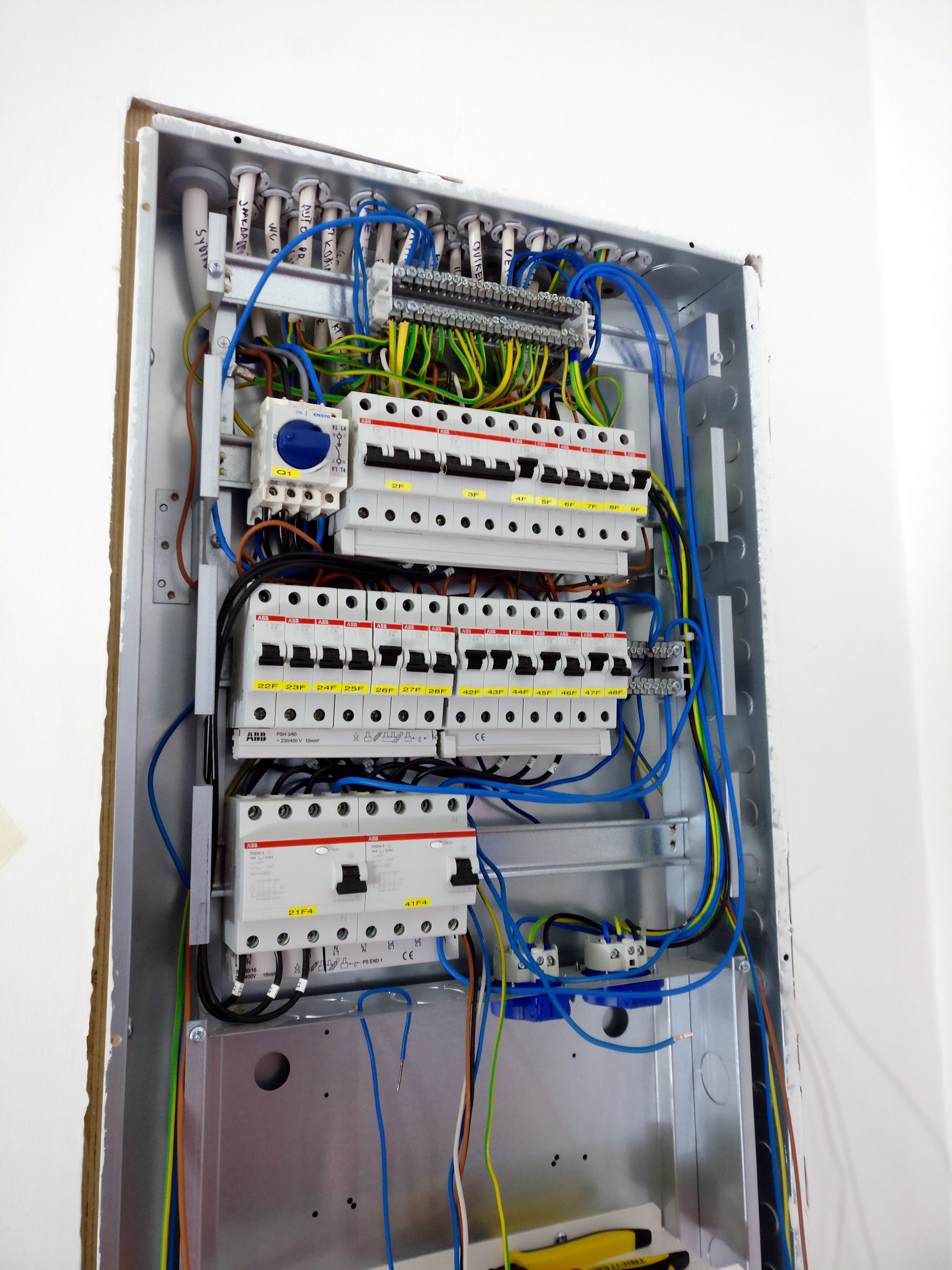
A circuit breaker is designed to interrupt current when specified overload or fault conditions occur. In a solar installation, breakers may be installed at the inverter output, at the incoming supply, and on individual distribution circuits.
When selecting a breaker, consider its rated current, voltage rating, breaking capacity, trip characteristics, number of poles, cable capacity, and coordination with other protective devices. A breaker must be capable of safely interrupting the prospective short-circuit current at its installation point.
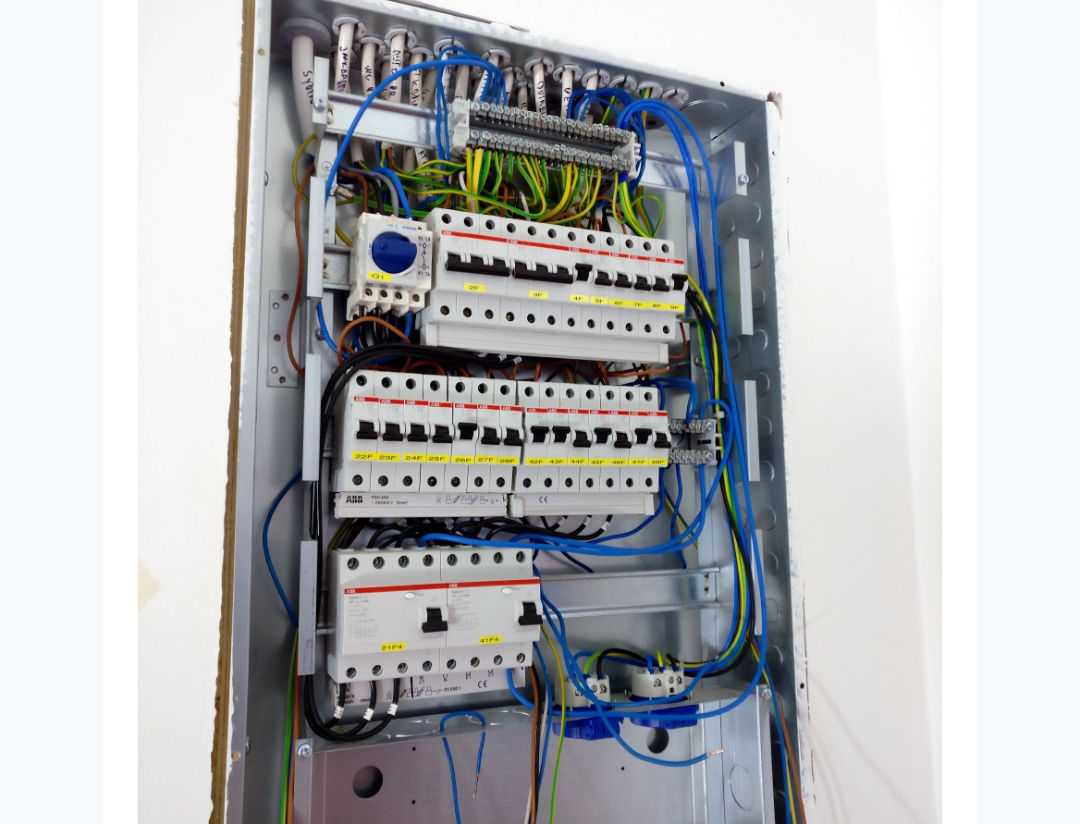
The AC distribution board is where power is distributed to the relevant circuits and protective devices are installed. Depending on the system design, a solar installation may have a dedicated inverter AC protection board, a main distribution board, or both.
A well-designed board should be enclosed, accessible for maintenance, correctly labelled, and suitable for the installation environment. Neutral and protective-earth conductors must be terminated at their appropriate bars; they should not be combined indiscriminately.
3. Inverter Output Protection
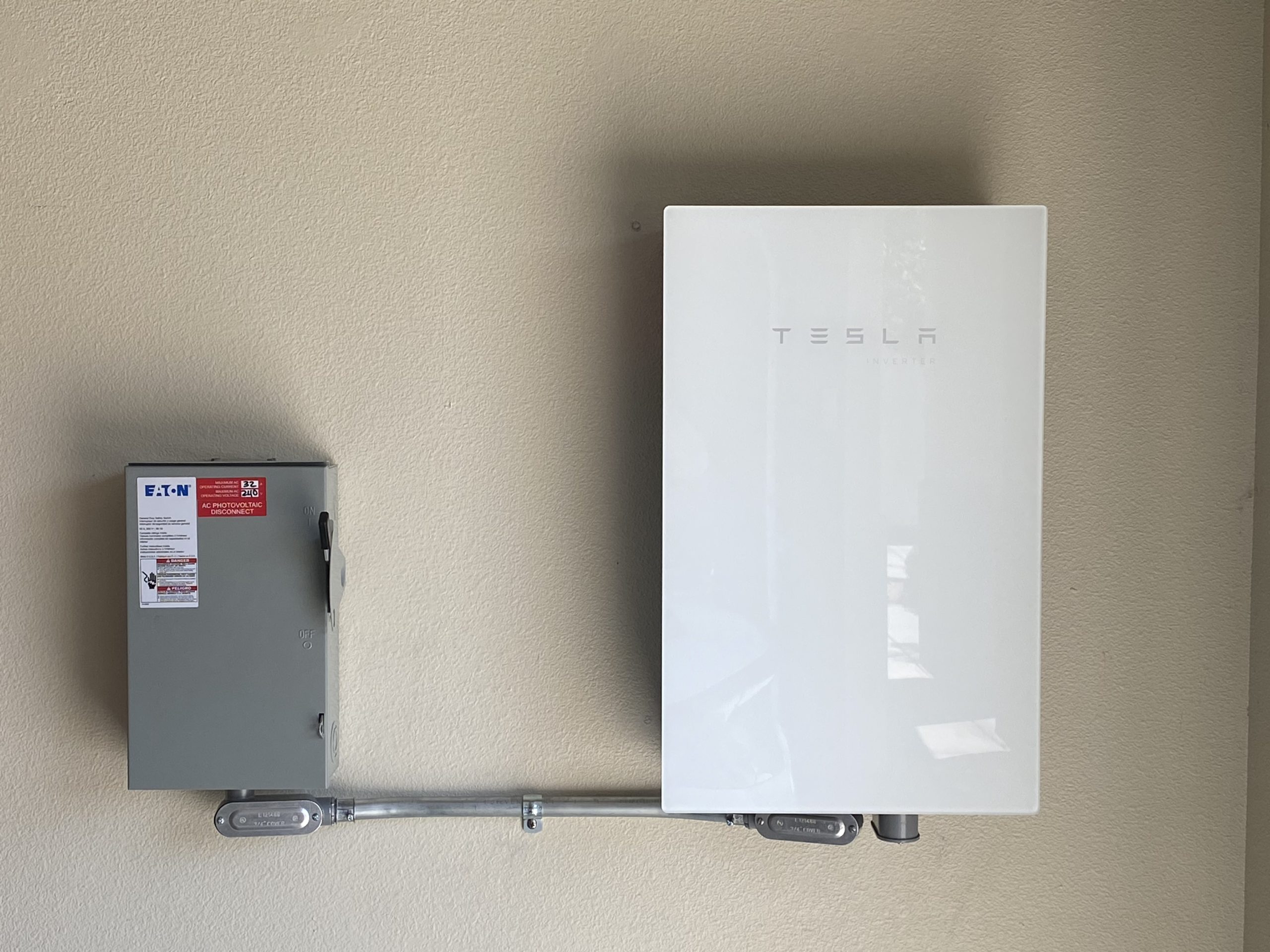
An inverter converts DC energy from solar panels or batteries into AC electricity. Its AC output must be protected against faults on the connected circuit. The protective device should be selected according to the inverter’s rated and maximum output current, cable capacity, prospective fault current, and the manufacturer’s instructions.
For a single-phase inverter, a preliminary output-current estimate is:
AC current = Inverter output power ÷ (AC voltage × power factor)
For example, a 5 kW single-phase inverter operating at 230 V with a power factor of 1 has an approximate output current of:
5,000 ÷ (230 × 1) = 21.7 A
This calculation is a starting point, not an automatic breaker selection. The inverter’s maximum specified current, cable capacity, installation conditions, and applicable standards must be checked before choosing the protective device.
An inverter’s internal electronic protection does not automatically replace the external circuit protection required by the installation design. Internal protection, circuit breakers, and isolation devices perform related but distinct functions.
4. Coordination Between Circuit Breakers and Cables
A protective device must be coordinated with the conductor it protects. For a typical overload-protection arrangement, the design current, protective-device rating, and corrected cable current-carrying capacity must satisfy the applicable coordination rules.
Design current ≤ Protective-device rating ≤ Corrected cable current-carrying capacity
Cable capacity may need adjustment for installation method, ambient temperature, grouping with other cables, and other relevant conditions. Additional checks are required for short-circuit protection and conductor thermal withstand.
A common mistake is installing a larger breaker simply because the inverter trips under heavy load. Investigate the cause first. The issue could involve overload, cable undersizing, incorrect settings, poor connections, or an unsuitable protective device.
5. RCDs and RCBOs in Solar Installations
Residual current devices detect an imbalance between the currents flowing through the relevant live conductors. Depending on the device and installation, they may provide additional protection against electric shock and certain earth-leakage faults.
An RCD does not provide general overload or short-circuit protection unless it is combined with an overcurrent protective function, as in an RCBO.
The correct RCD type and arrangement depend on the inverter design, residual-current characteristics, manufacturer’s instructions, and applicable standards. Do not assume that every inverter requires the same RCD configuration.
6. Common AC Protection Mistakes
- Using an oversized breaker without verifying the cable’s current-carrying capacity.
- Ignoring the breaker’s short-circuit breaking capacity.
- Treating an isolator as if it automatically provides overcurrent protection.
- Creating unintended neutral-earth connections.
- Ignoring backup circuits on hybrid inverters.
- Failing to label the inverter, grid, generator, and backup circuits.
- Assuming every inverter model uses the same protection arrangement.
7. AC Protection Inspection and Commissioning Checklist
- Confirm the inverter’s rated and maximum AC output current.
- Verify the AC cable size and corrected current-carrying capacity.
- Check breaker voltage, current, and breaking-capacity ratings.
- Confirm the inverter output isolation arrangement.
- Verify the RCD or RCBO type and operation where applicable.
- Inspect the AC SPD and its connections where fitted.
- Check terminal tightness using the specified torque values.
- Verify neutral and protective-earth terminations.
- Confirm circuit labels and warning notices.
- Carry out the required electrical tests using suitable instruments and procedures.
- Record test results and resolve defects before commissioning.
Conclusion
AC protection is more than installing a circuit breaker between the inverter and the distribution board. It requires a coordinated design that considers current, voltage, cable capacity, fault levels, isolation, residual-current protection, surge protection, and earthing.
Always consult the inverter manufacturer’s documentation and the applicable electrical installation standards. Where the design or fault level is uncertain, seek assistance from a qualified electrical professional.